by Contributed | Sep 23, 2020 | Uncategorized
This article is contributed. See the original author and article here.
In a cloud services world the quality of your network connectivity can make or break user experiences. Microsoft publishes best practices and principles of network connectivity to support customers with this work. We are making a broadly available preview available today for test tooling that identifies how well these principles are followed in the Microsoft 365 Admin Center and in the standalone Microsoft 365 network connectivity test tool.
Microsoft 365 Admin Center network connectivity functionality is available as public preview from today. Any customer in the worldwide commercial service can go to the Health -> Network Connectivity menu blade and request access to the preview. Preview acceptance is typically immediate, and participation has no impact to your organization outside access to these new pages.
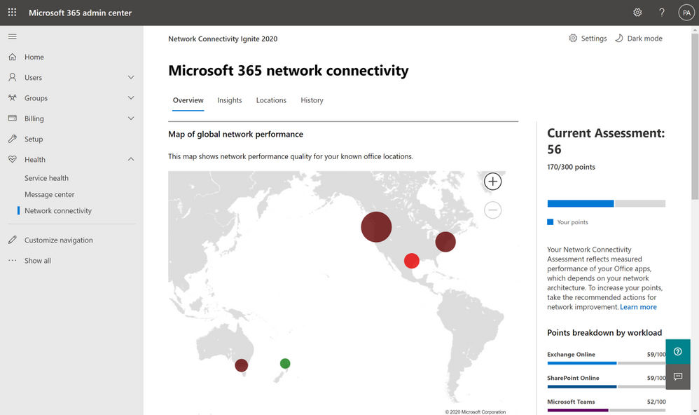
 Network connectivity page in the Microsoft 365 Admin Center
In the network connectivity pages you can see a network assessment that evaluates the impact of your network design on user experience in a 0 – 100 scale. This is calculated based on network attributes which have been proven through support cases to affect user experience the most. The network assessment is best evaluated at a specific office location, but an organization wide network assessment is also provided. The organization wide network assessment is also included in your productivity score. In addition, specific network insights are provided which identify network design improvements that could be made to align with the published network connectivity principles and improve network performance.
Office location identification options
It’s important to have network design configured well at each office location. We have three alternatives for you to associate the network tests with your office locations.
 Location detection icon
- You can enable Windows Location Services and consent to it on each client machine. The network telemetry in Microsoft 365 clients will detect this and will round it to a maximum accuracy of 300m x 300m before use. Reports are provided for your organization aggregated to the city resolution. This method of office location detection is relatively automatic but does require your corporate policy to allow for Windows Location Services to be enabled on client machines.
 Location LAN subnet entry icon
- Alternatively, you can enter each office location and specify the LAN Subnet used at that location. Because LAN Subnets need to be unique within your WAN for routing purposes, we can correlate network test measurements with the office locations you have entered. This has the added advantage that you are not limited to a single office location in each City, but you can monitor multiple so long as you enter the LAN Subnets separately.
 Location user-submitted report icon
- A third method for office location identification is more manual where you can have a user at each office location run a set of tests which are submitted back to your organization. This single test result collected by the Microsoft 365 network connectivity test tool is then used to be representative of the office location. One advantage of the stand-alone test tool is that the test will show up immediately in the admin center because there is no overnight aggregation required.
Whichever method you choose for office location identification, you will get the same rich reporting, network assessments, and network insights provided to help improve your network design.
Microsoft 365 network connectivity test tool
Microsoft 365 network connectivity test (http://connectivity.office.com) is also now in preview and enables sign-in to the users tenant and several ways to share test reports.
 Home page of connectivity.office.com
The Microsoft 365 network connectivity test tool is a standalone web site that allows users to test network connectivity between a user and Microsoft 365 service front doors. It runs at the user location and is run by someone at that location from their computer. It identifies common enterprise customer network design issues that violate published Microsoft 365 network connectivity principles and that impact user experience. It includes JavaScript based testing and a downloadable advanced test tool. These tests can be run anonymously, and the report is shown to the user only. The tool can be run while signed into the Microsoft 365 tenant and test reports run while signed in are shared to the Microsoft 365 Admin Center, they are shared with Microsoft employees, and may be shared with other users through an anonymous report link.
Release timeline
We are planning for a supported general availability release of these tools in the North American winter. Please share your feedback with us as we continue to improve on them.
SD-WAN configuration
As announced at last year’s Ignite conference, we’ve partnered with Cisco to bring a new feature to Microsoft 365 which we are calling “informed network routing.” This feature will allow for SD-WAN branch routers to select the best possible path for Microsoft 365 traffic, going beyond the traditional simplistic ping or HTTP probe, and now allowing direct integration of a feedback channel directly from the major applications that make up the Microsoft 365 service including Exchange, Teams, and SharePoint. This means that branch routers can now understand the end-user experience across these applications within the scope of the branch, allowing for quick response to any network quality issues that may occur on an individual path. An initial private preview of this technology is now in progress, and we look forward to announcing a broader preview in the coming weeks, as well as further industry partnerships to extend the availability of this technology.
References
Watch our network connectivity Ignite 2020 videos
http://aka.ms/netvideos
Discuss these features on our forums
http://aka.ms/netforums
Link back to this blog post
http://aka.ms/netignite
by Contributed | Sep 23, 2020 | Uncategorized
This article is contributed. See the original author and article here.
Log Analytics time picker is an easy way to scope and control the query’s time scope – directly from the UI without composing or altering your query code.
Time picker is also a great way to narrow down queries and zoom into the specific time where issues occurred.
The Log Analytics team has improved the way our time picker works.
We are happy to announce that that time picker now supports changing the query’s time span – even if a time scope has been specified in the query!
How it works:
If your query doesn’t contain a time scope – simply use the time picker to define the scope of time for your query.
Note that the default is 24 hours.
If your query specifies time – you can use the time picker to further narrow down the time scope:

Note: time scope will work in tandem with the time defined in the query. For example, If you defined a time span of 24 hours in your query and then used the time picker to define a 2 hour time span – your query result will show results from the last 2 hours.
You can always go back to the time set in query by selecting this option from the time picker:

Advanced options:
Log Analytics allows the selection of a specific time span, using the time picker.
You can click the ‘custom’ option in the time picker and specify your desired time:

This functionality makes specifying exact periods of time a breeze.
Summary:
Time picker is a great and easy way to specify time ranges for queries in Log Analytics.
Using the time picker saves a lot of time when composing queries and the fact that the time is a dynamic part of the UI makes time based exploration a breeze.
Feedback:
Let us know what you think! please share your thoughts and comments about this enhancement in the comments section of this blog!

by Contributed | Sep 23, 2020 | Uncategorized
This article is contributed. See the original author and article here.
My name is John Marlin and I am with the High Availability and Storage Team. With newer versions of Windows Server and Azure Stack HCI on the horizon, it’s time to head to the archives and dust off some old information as they are in need of updating.

In this blog, I want to talk about Failover Clustering and Networking. Networking is a fundamental key with Failover Clustering that sometimes is overlooked but can be the difference in success or failure. In this blog, I will be hitting on all facets from the basics, tweaks, multi-site/stretch, and Storage Spaces Direct. By no means should this be taken as a “this is a networking requirement” blog. Treat this as more of general guidance with some recommendations and things to consider. Specific requirements for any of our operating systems (new or old) will be a part of the documentation (https://docs.microsoft.com) of the particular OS.
In Failover Clustering, all networking aspects are provided by our Network Fault Tolerant (NetFT) adapter. Our NetFT adapter is a virtual adapter that is created with the Cluster is created. There is no configuration necessary as it is self-configuring. When it is created, it will create its MAC Address based off of a hash of the MAC Address of the first physical network card. It does have conflict detection and resolution built in. For the IP Address scheme, it will create itself an APIPA IPv4 (169.254.*) and IPv6 (fe80::*) address for communication.
Connection-specific DNS Suffix . :
Description . . . . . . . . . . . : Microsoft Failover Cluster Virtual Adapter
Physical Address. . . . . . . . . : 02-B8-FA-7F-A5-F3
DHCP Enabled. . . . . . . . . . . : No
Autoconfiguration Enabled . . . . : Yes
Link-local IPv6 Address . . . . . : fe80::80ac:e638:2e8d:9c09%4(Preferred)
IPv4 Address. . . . . . . . . . . : 169.254.1.143(Preferred)
Subnet Mask . . . . . . . . . . . : 255.255.0.0
Default Gateway . . . . . . . . . :
DHCPv6 IAID . . . . . . . . . . . : 67287290
DHCPv6 Client DUID. . . . . . . . : 00-01-00-01-26-6B-52-A5-00-15-5D-31-8E-86
NetBIOS over Tcpip. . . . . . . . : Enabled
The NetFT adapter provides the communications between all nodes in the cluster from the Cluster Service. To do this, it discovers multiple communication paths between nodes and if the routes are on the same subnet or cross subnet. The way it does this is through “heartbeats” through all network adapters for Cluster use to all other nodes. Heartbeats basically serve multiple purposes.
- Is this a viable route between the nodes?
- Is this route currently up?
- Is the node being connected to up?
There is more to heartbeats, but will defer to my other blog No Such Thing as a Heartbeat Network for more details on it.
For Cluster communication and heartbeats, there are several considerations that must be taken into account.
- Traffic uses port 3343. Ensure any firewall rules have this port open for both TCP and UDP
- Most Cluster traffic is lightweight.
- Communication is sensitive to latency and packet loss. Latency delays could mean performance issues, including removal of nodes from membership.
- Bandwidth is not as important as quality of service.
Cluster communication between nodes is crucial so that all nodes are currently in sync. Cluster communication is constantly going on as things progress. The NetFT adapter will dynamically switch intra-cluster traffic to another available Cluster network if it goes down or isn’t responding.
The communications from the Cluster Service to other nodes through the NetFT adapter looks like this.

- Cluster Service plumbs network routes over NIC1, NIC2 on NetFT
- Cluster Service establishes TCP connection over NetFT adapter using the private NetFT IP address (source port 3343)
- NetFT wraps the TCP connection inside of a UDP packet (source port 3343)
- NetFT sends this UDP packet over one of the cluster-enabled physical NIC adapters to the destination node targeted for destination node’s NetFT adapter
- Destination node’s NetFT adapter receives the UDP packet and then sends the TCP connection to the destination node’s Cluster Service
Heartbeats are always traversing all Cluster enabled adapters and networks. However, Cluster communication will only go through one network at a time. The network it will use is determined by the role of the network and the priority (metric).
There are three roles a Cluster has for networks.
Disabled for Cluster Communications – Role 0 – This is a network that Cluster will not use for anything.
Enabled for Cluster Communication only – Role 1 – Internal Cluster Communication and Cluster Shared Volume traffic (more later) are using this type network as a priority.
Enabled for client and cluster communication – Role 3 – This network is used for all client access and Cluster communications. Items like talking to a domain controller, DNS, DHCP (if enabled) when Network Names and IP Addresses come online. Cluster communication and Cluster Shared Volume traffic could use this network if all Role 1 networks are down.
Based on the roles, the NetFT adapter will create metrics for priority. The metric Failover Cluster uses is not the same as the network card metrics that TCP/IP assigns. Networks are given a “cost” (Metric) to define priority. A lower metric value means a higher priority while a higher metric value means a lower priority.
These metrics are automatically configured based on Cluster network role setting.
Cluster Network Role of 1 = 40,000 starting value
Cluster Network Role of 3 = 80,000 starting value
Things such as Link speed, RDMA, and RSS capabilities will reduce metric value. For example, let’s say I have two networks in my Cluster with one being selected and Cluster communications only and one for both Cluster/Client. I can run the following to see the metrics.
PS > Get-ClusterNetwork | ft Name, Metric
Name Metric
—- ——
Cluster Network 1 70240
Cluster Network 2 30240
The NetFT adapter is also capable of taking advantage of SMB Multichannel and load balance across the networks. For NetFt to take advantage of it, the metrics need to be < 16 metric values apart. In the example above, SMB Multichannel would not be used. But if there were additional cards in the machines and it looked like this:
PS > Get-ClusterNetwork | ft Name, Metric
Name Metric
—- ——
Cluster Network 1 70240
Cluster Network 2 30240
Cluster Network 3 30241
Cluster Network 4 30245
Cluster Network 5 30265
In a configuration such as this, SMB Multichannel would be used over Cluster Networks 2, 3 and 4. From a Cluster communication and heartbeat standpoint, multichannel really isn’t a big deal. However, when a Cluster is using Cluster Shared Volumes or is a Storage Spaces Direct Cluster, storage traffic is going to need higher bandwidth. SMB Multichannel would fit nicely here so an additional network card or higher speed network cards are certainly a consideration.
In the beginning of the blog, I mentioned latency and packet loss. If heartbeats cannot get through in a timely fashion, node removals can happen. Heartbeats can be tuned in the case of higher latency networks. The following are default settings for tuning the Cluster networks.
|
Parameter
|
Windows 2012 R2
|
Windows 2016
|
Windows 2019
|
|
SameSubnetDelay
|
1 second
|
1 second
|
1 second
|
|
SameSubnetThreshold
|
5 heartbeats
|
10 heartbeats
|
20 heartbeats
|
|
CrossSubnetDelay
|
1 second
|
1 second
|
1 second
|
|
CrossSubnetThreshold
|
5 heartbeats
|
10 heartbeats
|
20 heartbeats
|
|
CrossSiteDelay
|
N/A
|
1 second
|
1 second
|
|
CrossSiteThreshold
|
N/A
|
20 heartbeats
|
20 heartbeats
|
For more information on these settings, please refer to the Tuning Failover Cluster Network Thresholds blog.
Planning networks for Failover Clustering is dependent on how it will be used. Let’s take a look at some of the common network traffics a Cluster would have.

If this were a Hyper-V Cluster running virtual machines and Cluster Shared Volumes, Live Migration is going to occur. Clients are also connecting to the virtual machines.
Cluster Communications and heart beating will always be on the wire. If you are using Cluster Shared Volumes (CSV), there will be some redirection traffic.
If this were Cluster that used ISCSI for its storage, you would have that as a network.
If this was stretched (nodes in multiple sites), you may have the need for an additional network as the considerations for replication (such as Storage Replica) traffic.
If this is a Storage Spaces Direct Cluster, additional traffic for the Storage Bus Layer (SBL) traffic needs to be considered.
As you can see, there is a lot of various network traffic requirements depending on the type of Cluster and the roles running. Obviously, you cannot have a dedicated network or network card for each as that just isn’t always possible.
We do have a blog that will help with the Live Migration traffic to get some of the traffic isolated or limited in the bandwidth it uses. The blog Optimizing Hyper-V Live Migrations on an Hyperconverged Infrastructure goes over some tips to set up.
The last thing I wanted to talk about is with stretch/multisite Failover Clusters. I have already mentioned the Cluster specific networking considerations, but now I want to talk about how the virtual machines react in this type environment.
Let’s say we have two datacenters and a four-node Failover Cluster with 2 nodes in each datacenter. As with most datacenters, they are in their own subnet and would be similar to this:

The first thing you want to consider is if you want security between the cluster nodes on the wire. As a default, all Cluster communication is signed. That may be fine for some, but for others, they wish to have that extra level of security. We can set the Cluster to encrypt all traffic between the nodes. It is simply a PowerShell command to change it. Once you change it, the Cluster as a whole needs to be restarted.
PS > (Get-Cluster).SecurityLevel = 2
0 = Clear Text
1 = Signed (default)
2 = Encrypt (slight performance decrease)
Here is a virtual machine (VM1) that has an IP Address on the 1.0.0.0/8 network and clients are connecting to it. If the virtual machine moves over to Site2 that is a different network (172.0.0.0/16), there will not be any connectivity as it stands.
To get around this, there are basically a couple options.
To prevent the virtual machine from moving from a Cluster-initiated move (i.e. drain, node shutdown, etc), consider using sites. When you create sites, Cluster now has site awareness. This means that any Cluster-initiated move will always keep resources in the same site. Setting a preferred site will also keep it in the same site. If the virtual machine was to ever move to the second site, it would be due to a user-initiated move (i.e. Move-ClusterGroup, etc) or a site failure.
But you still have the IP Address of the virtual machine issue to deal with. During a migration of the virtual machine, one of the very last things is to register the name and IP Address with DNS. If you are using a static IP Address for the virtual machine, a script would need to be manually run to change the IP Address to the local site it is on. If you are using DHCP, with DHCP servers in each site, the virtual machine will obtain a new address for the local site and register it. You then have to deal with DNS replication and TTL records a client may have. Instead of waiting for the timeout periods, a forced replication and TTL clearing on the client side would allow them to connect again.
If you do not wish to go that route, a virtual LAN (VLAN) could be set up across the routers/switches to be a single IP Address scheme. Doing this will not have the need to change the IP Address of the virtual machine as it will always remain the same. However, stretching a VLAN (not a recommendation by Microsoft) is not always easy to do and the Networking Group within your company may not want to do this for various reasons.
Another consideration is implementing a network device on the network that has a third IP Address that clients connect to and it holds that actual IP Address of the virtual machine so it will route clients appropriately. For example:

In the above example, we have a network device that has the IP Address of the virtual machine as 30.0.30.1. It will register this with all DNS and will keep the same IP Address no matter which site it is on. Your Networking Group would need to involved with this and need to control it. The chances of them not doing it is something to also consider if it can even done within your network.
We talked about virtual machines, but what about other resources, say, a file server? Unlike virtual machine roles, roles such as a file server have a Network Name and IP Address resource in the Cluster. In Windows 2008 Failover Cluster, we added he concept of “or” dependencies. Meaning, we can depend on this “or” that.

In the case of the scenario above, your Network Name could be dependent on 1.0.0.50 “or” 172.0.0.50. As long as one of the IP Address resources is online, the name is online and what is published in DNS. To go a step further for the stretch scenario, we have two parameters that can be used.
RegisterAllProvidersIP: (default = 0 for FALSE)
- Determines if all IP Addresses for a Network Name will be registered by DNS
- TRUE (1): IP Addresses can be online or offline and will still be registered
- Ensure application is set to try all IP Addresses, so clients can connect quicker
- Not supported by all applications, check with application vendor
- Supported by SQL Server starting with SQL Server 2012
HostRecordTTL: (default = 1200 seconds)
- Controls time the DNS record lives on client for a cluster network name
- Shorter TTL: DNS records for clients updated sooner
- Disclaimer: This does not speed up DNS replication
By manipulating these parameters, you will have quicker connection times by a client. For example, I want to enable to register all the IP Addresses with DNS but I want the TTL to be 5 minutes. I would run the commands:
PS > Get-ClusterResource FSNetworkName | Set-ClusterParameter RegisterAllProvidersIP 1
PS > Get-ClusterResource FSNetworkName | Set-ClusterParameter HostRecordTTL 300
When setting the parameters, recycling (offline/online) of the resources is needed.
There is more I could go into here with this subject but need to signoff for now. I hope that this gives you some basics to consider when designing your Clusters while thinking of the networking aspects of it. Networking designs and considerations must be carefully thought out.
Happy Clustering !!
John Marlin
Senior Program Manager
High Availability and Storage
Follow me on Twitter: @johnmarlin_msft
by Contributed | Sep 23, 2020 | Uncategorized
This article is contributed. See the original author and article here.
You can now personalize your tasks with custom fields in Project for the web! Select the “New field” button under the Add column menu to get started.
Create up to ten new fields to help you keep track of important information specific to your projects and workflows. Choose from four types:
- Track important deadlines with Date fields
- Use Yes/No fields to flag tasks that need follow up
- Use Number fields to manage details such as quantities
- Take short notes about status with Text fields
Filter tasks using the contents of fields. If you have limited screen real estate, manage the fields in the task details pane. Give them a try, and let us know what you think in our UserVoice forum.

How to create custom fields

Select the “Add column” button to see the “New field” option. This button will open the menu to create a new custom field.

From here, select the type of custom field you would like to create.

Give your field a name select ‘Create’ to create your new custom field.

Your new custom field will appear in your project and you can start using it.

Like any other field, custom fields can be hidden from the Grid view. You can also use the column header to reach the edit pane where you can edit your fields.

The Edit field dialog box allows you to rename or delete that field.

Custom fields also have their own section in the task details pane. This is a great view if you have limited space on your screen.
Frequently asked questions
Q: How can I create the same custom fields on all my projects?
A: If you want to use the same set of custom fields in all your projects, you can create a template project, and then copy it. All your fields and values will be copied over. Take a look at our article on copying projects.
Q: Can I create formulas in Project for the web?
A: Not today. We’d love to learn more about what kinds of things you’d use formulas for. Provide your feedback in our User Voice forum.
Q: Can I include these fields in PowerBI reports for Project for the web?
No. These fields are local to your projects.
Q: How many custom fields can I create in one project?
A: Each project can support up to 10 custom fields
Feedback!
Microsoft Project loves your feedback!
We monitor the comments on all blog posts, so please let us know what you think about this feature in the comments section below. Additionally, the feedback you provide through the “Feedback” button in the product plays a vital role in our product decisions. Please let us know what you think. We read every submission and try to respond as needed; be sure to provide an email address so we can reach out for further information.
The feedback you provide through UserVoice for Project for the web gives us new ideas on how to improve your experience with Project. Join an ongoing discussion, or start your own conversation. We love to read what people think on making Project even better.

Recent Comments